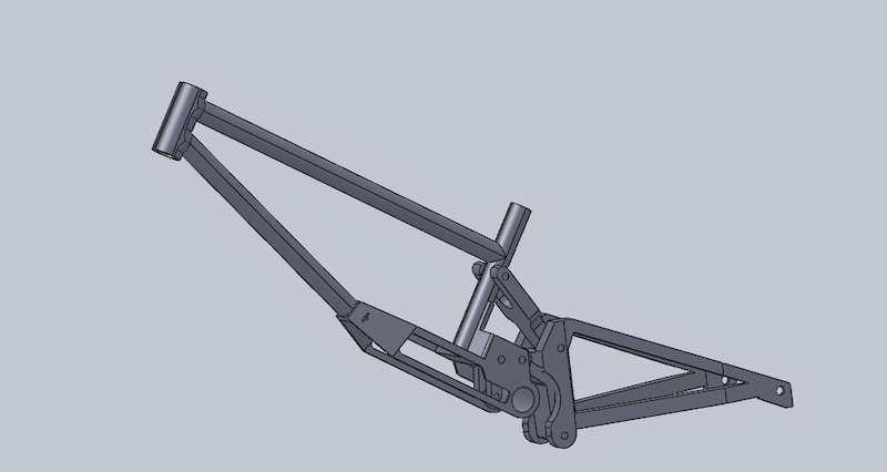
rough mock up to make sure the principle works i amde today. main aims, rearwards axle path, really low standover, and really low centre of gravity.
idler pulley not on there yet, and it wont look exactly like this as its got to be makeable.

545
Views
10
Comments
0
Favs
Photo info
- Album
- frame-design
- Category
- Bikes - DH
- Date Posted
- Apr 30, 2011 at 13:36Apr 30, 2011
- Location
-
Plymouth, United Kingdom

Photo details
- Photo Size:
- Camera
- unknown unknown
10 Comments
- 1 0
standard gear sized, milled out for bearings and linkage fitting. The shock stroke should limit the movement of the upper link. Am currently toying with high single pivot versions to make idler pulley versions easier too. will see how it goes, but running the model in solidworks has shown no inversion issues on the top link, it follows the same path as the bottom one 
Its not gonna be light, but hopefully around 15lbs maximum
Its not gonna be light, but hopefully around 15lbs maximum
- 1 0
Chaz just thinking a little and on your gears dont make them complete circles. They would not have to rotate a complete 360. Make the last teeth on each side large so that they cant possible rotate the wrong direction
- 1 0
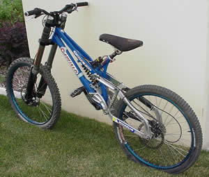
Looks like a brooklyn.... which means I love this design ... anything that reminds me of one is a winner!
- 1 0
Looks rad, have you run the pivot placements etc through linkage? Looks like it could be quite rear heavy though?
- 1 0
not yet, but done it all down on papr, with axle paths etc and it all works. Rear triangle was done in a rush, currently working on the proper one, will be skinny diameter steel in reality with chunky alloy links. so not too bad
- 1 0
looks more like a canfield, and works the same way too.
www.bikeaddict.com/bikes/images/fattyfatleft.jpg
www.bikeaddict.com/bikes/images/fattyfatleft.jpg
and how/where you gonna get gears for the shock? kinda odd choice but i like how you could vary the shock ratio just by changing gears.