Specialized Patents Strange Air Shock - Shock Week 2023

Specialized are no strangers to innovative in-house suspension. Who could forget the 2007 Enduro with its 150 mm dual-crown fork, complete with a 25 mm thru-axle, mounted to a bike that weighed less than 28 pounds? Then there's Specialized's Brain system, which automatically locks and unlocks the shock and fork depending on the terrain; it's been around since 2002 - decades before Fox Live Valve or RockShox Flight Attendant got in on the act - and is still going strong.
It looks like The Big S is still working on new ideas. In March 2023 they published a patent showing various designs of air spring that feature at least one extra air chamber. Depending on the design, air could be allowed to flow between the main chamber and the extra chamber(s) in some of the travel, but the extra chamber(s) could be shut off at some other point later in the stroke, in order to manipulate the spring curve (how the force changes with travel).
Specifically, it could be possible to have a very linear spring curve in the middle of the travel (30-70%) to absorb bumps, before the spring force ramps up abruptly towards the end of the travel in order to prevent bottom out. Unlike with conventional volume spacers, the end-stroke ramp could be tuned independently of the mid-stroke spring rate, and the end-stroke could be dramatically stiffer.
Here's an example of how it could work:

A view of what the "cup-shaped" air piston (marked 520) might look like in real life.

A cross-section of this design of air spring in the extended position.

A cross-section of the same air spring in the compressed position.
Closing off the extra chamber with a cup-shaped piston
In this embodiment (one of the simpler designs discussed in the patent), the air spring piston (which is numbered 520 in the above diagrams) is cup-shaped. The air spring chamber has an outer sleeve that air can flow in and out of during most of the travel (this is similar to many existing shocks such as a Fox Float X2 or RockShox Monarch). In the first ~70% of the travel (as shown in the diagram on the bottom left) holes in the outer wall of the main chamber (417) allow air to flow into and out of the second chamber (113) via channels (413). As the shock is compressed, the air in both chambers (111 and 113) compresses together, creating a large effective volume and a linear spring curve.
However, at some point late in the travel (after 70%), the cup-shaped piston (520) blocks off the holes (417). This closes off the extra air chamber (113) from the main chamber (111). This is shown in the bottom-right diagram, where "+" indicates air that is still being compressed, while "X" represents air that is no longer affected by the piston. From this point on, the effective volume of the air spring is much smaller, and so the spring abruptly becomes much more progressive. The effect of this can be seen in the below graph.

Force-displacement curve for the spring design described above. The solid lines represent a typical air spring (one line for compression and one for rebound) while the dashed lines represent the curve for the spring described above.
In this graph, you can see how this design of air spring has a dramatic uptick in spring rate (the gradient of the force-travel curve) starting at around 40 mm (80%) of travel. The point of this design is that the uptick in spring rate in the last ~20% of travel is independent of the (relatively linear) spring rate in what Specialized call the "bump zone" (30-70% travel). In contrast, adding volume spacers affects the mid-stroke somewhat, with no distinct change in spring rate between the mid-stroke and end-stroke.
Specifically, the patent states that "the spring rate varies by no more than 20% between 30% and 70% travel, but at least 100% ... in the 70-98% 'bottom out zone'". In other words, my understanding is that they are claiming this design can remain close to linear in the mid-stroke, but at least double in spring rate between 70% travel and bottom-out. The point is, there's a distinct change in spring rate near the end of the travel (where the extra chamber is shut off), whereas with volume spacers, there's a gradual increase in spring rate through the middle and end stroke.
The patent also shows an even more extreme and complex approach to this.

A cross-section view of another design of air spring in the extended position.

A cross-section of the same air spring in the compressed position.
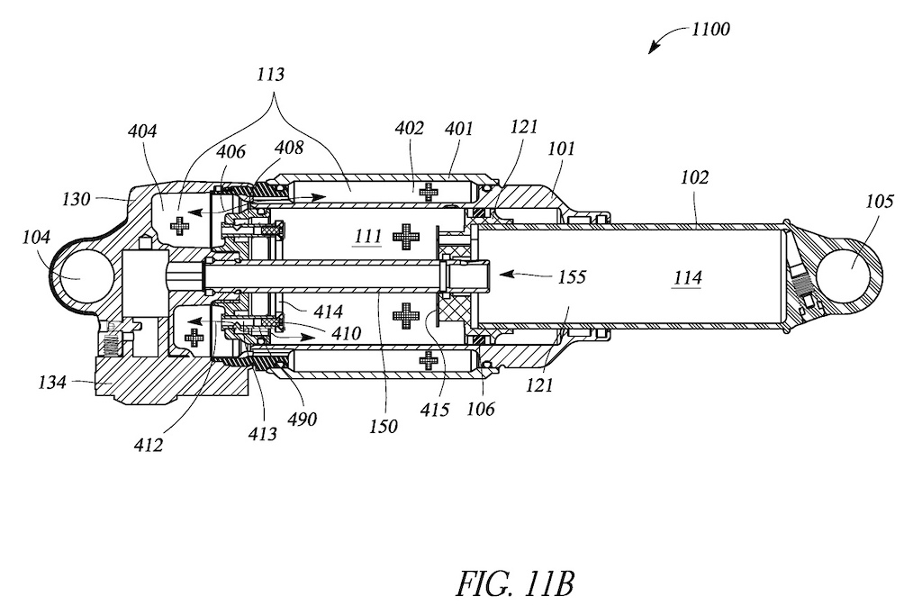
The plunger approach
This design has a spring-loaded plunger (410) that slides to the left when contacted by the piston (415), closing off a channel (417) and blocking airflow to both the cap of the shock (404) and the outer air sleeve (402). The figure on the right shows the volume of air that remains to be compressed with a "+" sign and the volume that's cut off with an "X". This design therefore results in an even more dramatic reduction in working volume than the one we looked at above, and this results in an even more dramatic increase in spring rate towards the end of the travel.

The force-travel curve for the air spring depicted in Figures 4A and 4b directly above is shown with a dashed line, while the solid line represents the spring curve for a conventional air spring.
In this graph, you can see how this design could result in an even more dramatic step change in spring force at a certain point late in the travel. The idea is to have a very linear spring curve in the majority of the stroke (for better bump absorption) while allowing higher or greater bottom-out resistance.

A fork air spring is depicted with an air sleeve (401) and extra air chamber (412) which would be closed off when the piston (520) passes the ports (423).
Later in the patent, there are several similar designs for fork air springs, with various different ways of closing off an extra air chamber towards the end of the travel, thereby achieving a similar step-up in spring rate. There's also a description of an air spring that could have multiple extra chambers that would be sealed off at multiple different points in the travel, thereby creating multiple upticks in the spring curve. One design even depicts a similar extra chamber connected to the negative spring, which would be closed off as the piston approaches full extension in the rebound direction. This would create an even steeper drop in spring force as the spring approaches full extension, sort of acting as an extra pneumatic top-out bumper.


Interestingly, the patent also depicts a shock with an extra positive air chamber (which Specialized refer to as the 'compensation chamber') located in a similar location to a conventional piggyback shock's damping reservoir, which could work much like the three-chamber air springs found in Ohlins, EXT and Manitou forks. The air in the compensation chamber (113) would be set to a higher pressure than the main chamber (111) such that the second piston (122) starts to move at the point in the travel where the air pressure in the main chamber exceeds the compensation chamber, after which the working volume of the positive chamber expands to include both chambers, as the second piston (122) slides freely.
Notice that this is effectively the opposite of the air springs discussed in the rest of the patent, in that the working volume of the air spring increases at some point in the travel, rather than decreases, making it more linear, not less progressive. My guess is that this design might have longer-travel bikes in mind, where mid-stroke support is more important than bottom-out resistance. As far as I understand it, this is conceptually similar to designs we've seen before (most notably with EXT's Aria shock), but Specialized's document suggests that the negative chamber could also be tuned independently of the two positive chambers: "The negative chamber can be configured to produce a lower spring rate..in the initial zone... In the bump zone, the primary chamber and compensation chamber can work together to closely follow the desired bump zone curve of a standard coil spring."
What's the point?
It's interesting to note that a common complaint we hear about air springs is a lack of support in the mid-stroke and excessive ramp-up towards bottom-out, and the designs that make up the bulk of the patent seem to double down on that theme by effectively reducing the air volume near the end of the travel. Perhaps a clue to its intended application lies in this passage from the patent: "the shorter travel bicycle [100 mm] can have a spring curve with a more linear slope in the first 0%-70% or 5%-70% of travel ... a longer travel bike can have a more linear spring curve in the bump zone and the majority of the ending zone. For example, 30% to 90% or 30%-95% of travel."
My interpretation of this is that a short-travel bike might benefit from a linear (and relatively soft) spring rate up to about 70% travel (for maximum compliance and traction), with a much stiffer spring rate thereafter to prevent bottom-out. Whereas, with a longer-travel bike (>150 mm travel), the problem is usually not preventing bottom-out but providing enough support in the middle of the travel, so a relatively linear spring curve is desirable right up to the end of the travel. So, I would conjecture that the more progressive designs discussed in the majority of the document are dreamed up with XC bikes in mind.
Although this may be too reductionist, I think this design could be thought of as a pneumatic bottom-out bumper; it provides a sudden increase in spring force in the last 20% of the travel, thereby allowing the first 80% to be set up softer to better deal with small-medium bumps. Whether this is advantageous is hard to say, but my guess is that if it does ever make it into reality, it would make the most sense on short-travel bikes.

Look out for a short travel Specialized with a shock that looks like this (but don't hold your breath).
Will it ever be produced?
We contacted Specialized to ask if they could tell us any more about this patent and - as is usually the case - they didn't want to give much away. This is all they could tell us:
 | Impressive catch of our patent application! Our Ride Dynamics team has a 24/7 obsession with improving the ride through advancing suspension, chassis design, and kinematic performance. When we hit on a concept that's promising, we pursue a patent. While we'd love to spill the beans about the tech you discovered and if/when it might see the dirt, it's just too early |
As a result, the above is merely my interpretation of the patent document - I have no extra information - so take it with a grain of salt.
Author Info:

Must Read This Week
Sign Up for the Pinkbike Newsletter - All the Biggest, Most Interesting Stories in your Inbox
PB Newsletter Signup
I totally forgot about auto sag, that didn't last long
That and it’s an extra thing to service, but if you follow service intervals then it’s really not a huge deal.
no, this is Neature. Look it up on youtube
Anyway, coaxial designs are essentially like putting a small water bottle in a slightly larger water bottle, and controlling the flow of air between the inner chambers and the outer chamber by how you design the way they connect. The point I'm trying to make though, is that a coaxial design increases the total volume available for air to occupy while it moves between chambers.
I'd think that Normally you'd want to increase the volume available for the oil chamber.... Odd design.
But, I don't think that would work out too well. It'd be very difficult. Air shocks are better at absorbing large impacts, and coils are better at absorbing faster repeated impacts. An air shock is going to inhibit the coil's performance, and vice versa. Theorhetically, you could have an in-line air shock "activate" once a coil is at ~60% stroke, providing much needed bottom out support on larger impacts. Idk. Someone smarter than me please do it.
enduro-mtb.com/en/dt-swiss-f-535-and-f-535-one-forks-test
It was ~10 years later that manitou brought the idea back to life with thier IRT